INSTALLATION
Traps should be installed in easily accessible position and location for easy servicing. The maximum differential pressure which is stamped on product name plate must be bigger than the maximum differential pressure of the whole system. Be sure to install trap horizontally to ensure proper operation.
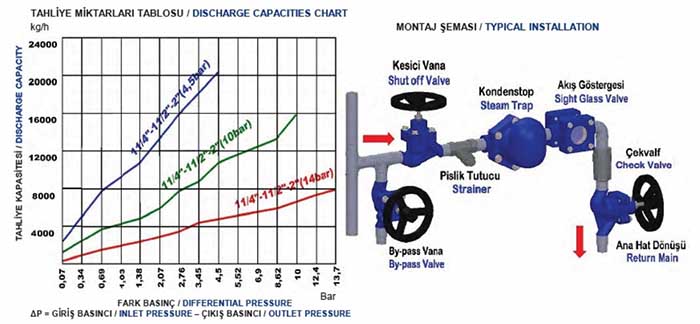
1.Install the trap below and close to the equipment which will drain and avoid long lenghts of horizontal piping ahead of trap.
2.Pitch all horizontal inlet lines towards the stream trap to help eliminate potential water hammer problems.
3.A strainer should always be installed ahead of trap.
4.Union fittings or flange connection and shut off valves should be installed on both sides of trap for ease of servicing and trap testing.
5.Install a test valve in outlet pipe and cap it,which allows trap to be tested. Cap is used as safety precaution when unit is not being tested.
6.Blowdown piping using full steam pressure for 5 minutes prior to service. This cleaning process will remove debris from the pipe-line.
7.Perform maintenance and cleaning 2/3 days after start-up until system is clean. Then perform maintenance every 6/12 months once in normal operation.
MAINTENANCE
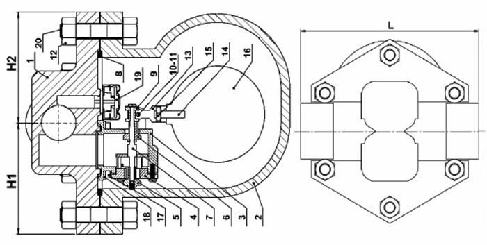
With timely check-up, regularly and properly maintenance, NORDSTEAM NST44TVE series will provide optimum performance and long life cycle. The internal components of steam trap can be replaced without removing the trap from the line. The trap mechanism should be inspected periodically and all dirt should be removed from working parts. Worn parts must be replaced with new ones. Whenever the bonnet of steam trap is taken apart always replace the gasket of the bonnet, with a new one.


 NST-44TVE