
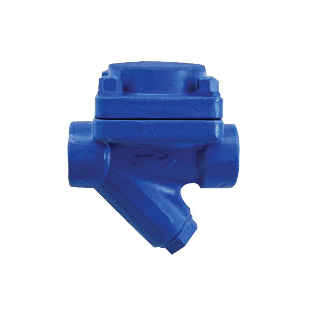

NST-TKD21 with the welded stainless steel bellows adjusts itself over entire operating pressure range. This element discharges the condensate at approximately 10º C - 20º C below steam saturation temperature and is also resistant to water hammer.
INSTALLATION
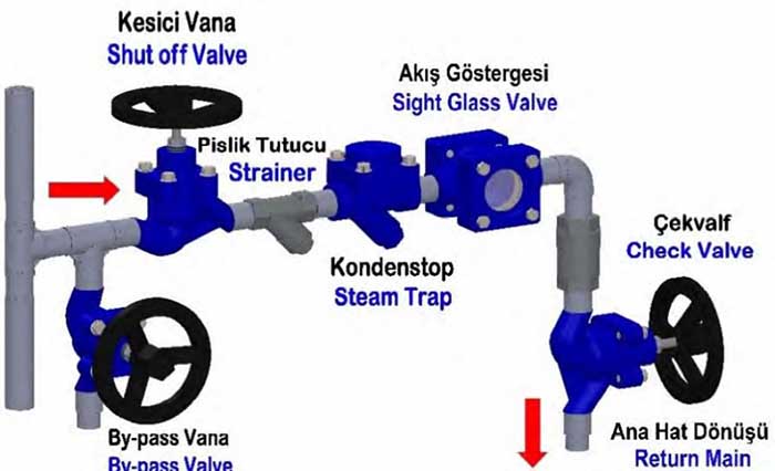
Traps should be installed in easily accessible position and location for easy servicing. The maximum differential pressure stamped on product name plate must be higher than the maximum pressure differential across the trap.
1.Pitch all horizontal inlet lines towards the stream trap to help eliminate potential water hammer problems.
2.A dirt pocket and strainer (with blow down) should always be installed before trap.
3.Union fittings or flange connection and shut off valves should be installed on both sides of trap for ease of servicing and trap testing.
4.Install a test valve in outlet pipe and cap it.This allows trap to be tested.
5.Blowdown piping using full steam pressure for (5) five minutes prior to service. This cleaning process will remove debris from piping.
6.Perform maintenance and cleaning 2/3 days after startup until system is clean. Then perform maintenance every 6/12 months in normal operation.
MAINTENANCE
When checked regularly and properly maintained, will provide optimum performance and long life. The mechanism should be inspected periodically and all dirt should be removed from working parts. Worn parts must be replaced. The safety measures for replacing a steam trap also apply for opening the cover or body of the steam trap. Always renew the gasket after disassembling the steam trap.
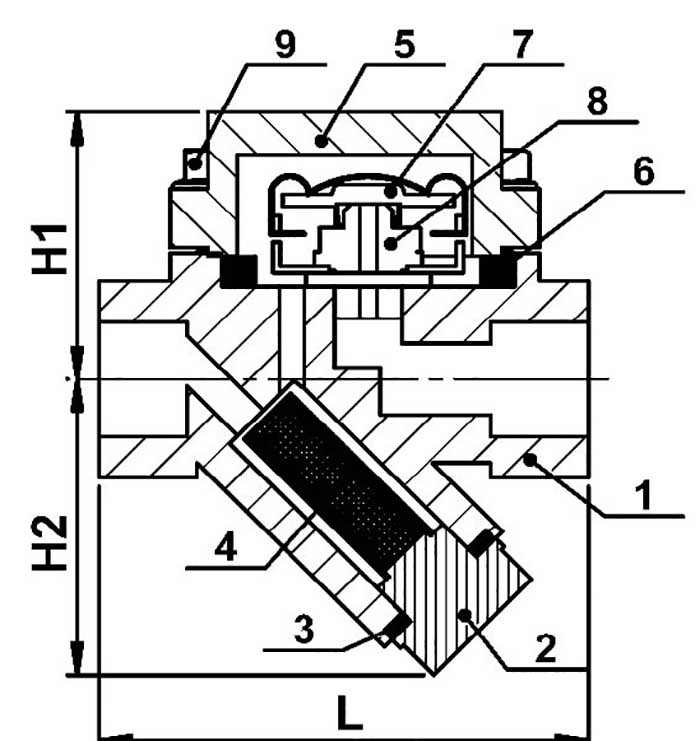
| SPARE PARTS | ||
| No | Description | Material |
| 1 | BODY | A105 |
| 2 | BLIND PLUG | 45 |
| 3 | PLUG GASKET | SS 304 |
| 4 | SCREEN | SS 304 |
| 5 | BONNET | A105 |
| 6 | BONNET GASKET | SS 304 + GRAPHITE |
| 7 | THERMOSTATIC ELEMENT | SS 304 |
| 8 | VALVE SEAT | 2Cr13 |
| 9 | BOLT | SAE Gr. 5 |
| DIMENSIONS | |||
| SIZE | L | H1 | H2 |
| 1/2 '' | 100 mm | 58 mm | 55 mm |
| 3/4 '' | 100 mm | 58 mm | 55 mm |
| 1″ | 120 mm | 60 mm | 55 mm |
| 11/4″ | 150 mm | 85 mm | 60 mm |
| 11/2″ | 150 mm | 85 mm | 60 mm |
| 2″ | 160 mm | 85 mm | 60 mm |
| CONNECTION | THREADED BSP | |||||
| Sizes | 1/2’’ | 3/4’’ | 1″ | 11/4″ | 11/2″ | 2″ |
| Weights (KG) | 1,82 | 2,04 | 2,2 | 3,8 | 4 | 4,2 |
| OPERATING CONDITIONS | |
| MAX. ALLOWABLE PRESSURE PMA (BAR) | 16 |
| MAX. ALLOWABLE TEMPERATURE TMA (ºC) | 250 |
| MAX. OPERATING PRESSURE PMO (BAR) | 10 |
| MAX. DIFFERENTIAL PRESSURE PMD (BAR) | 7 |
 NST-TKD21