
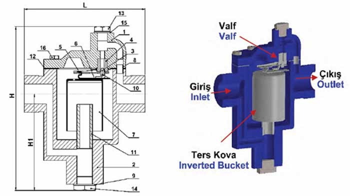

The Inverted Bucket Steam Trap is simply an automatic valve that opens for condensate and air but closes for steam. Steam entering the inverted submerged bucket causes the bucket to float and rise , by the effect of rising, closes the valve. But meanwhile condensate begins to enter the trap and also begins filling the bucket. The filling bucket begins sinking and opening the trap valve to discharge the condensate. Nordsteam inverted bucket steam traps have frictionless leverage system that multiplies the force made by the bucket, which forces the valve to open against pressure.
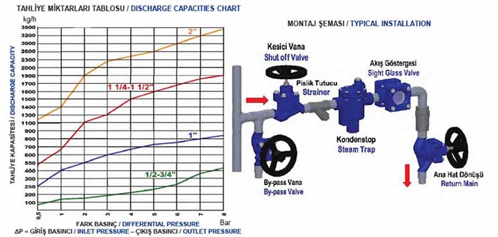
INSTALLATION
Traps should be installed in easily accessible position and location for easy servicing. The maximum differential pressure stamped on product name plate must be greater than the maximum pressure differential across the trap. The trap must be installed with the body horizontally so that bucket will rise and fall vertically. The inlet and outlet connections should be in a horizontal plane for horizontal traps and a vertical plane with inlet on the bottom for vertical traps. The trap should be installed below the drain point, so that a water seal can be maintained around the open end of the bucket.
1. Install the trap below and close to the equipment which will drain condensate, avoid long lenghts of horizontal piping ahead of trap.
2. Pitch all horizontal inlet lines towards the stream trap to help eliminate potential water hammer problems.
3. All models should have a strainer installed ahead of trap.
4. Union fittings and shut off valves should be installed on both sides of trap for ease of servicing and trap testing.
5. A test and pressure relief valve should be installed to assure relief of internal pressure prior to servicing.
6. A check valve should be installed on return piping if there will be a pressurized return line or the trap drains to an overhead return line.
Inverted bucket traps may need to be primed before being placed into service. Either of the following methods can be used.
1. Remove pipe plug from trap cover. Pour water into trap until full and replace pipe plug.
2. Keep return piping valve closed until trap fills with condensate, then slowly open valve.
MAINTENANCE
The trap mechanism should be inspected periodically and dirt should be removed from working parts. Worn parts must be replaced.
| SPARE PARTS | ||
| No | Description | Material |
| 1 | Bonnet | GG25 |
| 2 | Body | GG25 |
| 3 | Valve | SS 304 |
| 4 | Valve Seat | SS 304 |
| 5 | Lever | SS 304 |
| 6 | Bucket Clip | SS 304 |
| 7 | Bucket | SS 304 |
| 8 | Thimble | SS 304 |
| 9 | Gasket | Klingerite |
| 10 | Valve Clip | SS 304 |
| 11 | İnternal Tube | Steel Pipe |
| 12 | Gasket | SS 304 + Graphite |
| 13 | Bonnet Plug | Steel ST37 |
| 14 | Bottom Cover Plug | Steel ST37 |
| 15 | Gasket | Klingerite |
| 16 | Bonnet Bolt | SAE Gr.5 |
| DIMENSIONS | |||
| Size | L | H | H1 |
| 1/2 " | 140 mm | 170 mm | 90 mm |
| 3/4 " | 150 mm | 180 mm | 95 mm |
| 1 " | 170 mm | 190 mm | 100 mm |
| 1 1/4 " | 180 mm | 200 mm | 105 mm |
| 11/2 " | 220 mm | 235 mm | 120 mm |
| 2 " | 245 mm | 275 mm | 130 mm |
| CONNECTION | SCREWED BSP | |||||
| Sizes | 1/2" | 3/4" | 1" | 1 1/4" | 11/2" | 2" |
| Weights (KG) | 4,1 | 5,1 | 6,6 | 8,3 | 13,2 | 21,1 |
| OPERATING CONDITIONS | |
| Max. Allowable Pressure PMA (bar) | 24 |
| Max. Allowable Temperature TMA (ºC) | 220 |
| Max. Differential Pressure PMD (bar) | 5,5 - 8 |
| Max. Operating Pressure (bar) | 16 |
 NST-881HSP